FireFighting Robot
Smart Remote-Controlled Firefighting Robot
A fire is one of the most dangerous things that can happen in our lives and unfortunately it cannot be controlled in many cases, a single fire can destroy entire apartment blocks if left unattended for a long time, and with our constantly evolving cities firemen won’t be able to handle every fire that occurs, and that’s not taking into account that firemen usually get severely injured or burned.
The aim of this project is to create a robot to fight fires in places where humans cannot, the user controls it from a safe distance to put out fires and save lives using a remote control while getting visual feedback from a camera, using its various sensors the user can be provided with information to help assess the situation and guide their decision making.
The project has many applications, from personal use to industrial and governmental use, there’s also many recommendations to improve its design for commercial manufacturing.
Getting started
As shown in the infographic picture, the robot consists of two high-torque DC motors with metal gearbox, a water pump, a servo motor to direct the nozzle coming out of the pump and another to direct the onboard camera. As well as multiple sensors (temperature and ultrasonic) to provide the user with more data about the environment in which the robot is going through.
To apply this project, Arduino IDE is needed in order to control the ATMEGA328P chip on the UNO and NANO development boards.
Software
Configuring the nRF module and the servo motors as well as configuring the LiquidCrystal display for the controller is very important to get the project up and running. The data are collected from the joystick modules and switches on the controller, and then sent to the robot to process the data and control the motors accordingly.The flow of the code should be non-blocking to reach a fast-response system.
The following flow chart represents the code flow for the remote controller
The following flow chart represents the code flow for the robot
Ultrasonic Sensor
The gif represents the process of working of the ultrasonic sensor, when the trigger pin is triggered with a 10 μs pulse, the echo pin becomes logic high and transmits a sonic wave, then becomes logic low when it receives the wave again. Then the time is measured during this process and thus the distance ahead the sensor.

The measuring process is handled using pin change interrupt in order to reach a non-blocking code flow.
NRF module
In order to expect the best performance from the nRF modules, the TMRh20 RF24 library should be installed. Then the following lines should be used to configure the module. This step is very important for the module to work properly.
radio.begin();
radio.setChannel(125);
radio.setPALevel(RF24_PA_MAX);
radio.setRetries(4, 15);
radio.setAutoAck(true);
radio.enableDynamicPayloads();
radio.enableAckPayload();
radio.openWritingPipe(addresses[1]);
radio.openReadingPipe(1, addresses[0]);
The robot can operate easily using simple functions.
Hardware
The robot opertes at
12V as both the driving motors and the water pump operate at such voltage. Lithium-ion batteries are used to sypply the robot with power.
The circuits required to operate the robot at such voltage needs certain protection to limit the current drawn from the batteries and to protect the components.
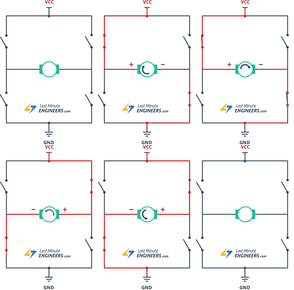
The motors are driven through an H-bridge circuit, the basic concept of such circuit is show in the following gif:

The circuits used for the Motor Driver and Pump Driver are designed using Eagle Autodesk. The remote controller operates at 9V as it doesn’t require operationa at a voltage higher than 5V. These photos and videos show glimpses of the procedures of the making of the circuits.
Mechanical Design
The body of the robot was designed using SOLIDWORKS. The circular design was chosen to increase the maneuverability of the robot and decrease the chances of side impacts the occurs to rectangualr geometry RCs. The design of the controller was designed in a way so that it would be easy ho hold in the hand and the buttons and joystick modules are easily reachable.
Features
- Can pump water to a distance of 4-6 meters ahead
- The nozzle can be directed to an angle of 30° to the right or the left
- Can be controlled from over 500 meters
- Visual feedback and feedback from temperature sensor and ultarsonic sensor are reported to the user through the controller continously
- The camera rotates such that it will always look at what the water is being pumped at.
Robot in action
The following videos show the robot in action being controlled by the controller and putting out small fires:
The robot and the remote: